- ATPG – Automatic test Pattern Generation
- Used to create a set of patterns, which can test the design for the faults as discussed in DFT-Fault models article. I would recommend reading DFT-Fault models to understand this article better.
- Has two main steps: Generate patterns, Perform fault simulation to check which faults can be detected by those patterns.
- There are two kinds of patterns:
Random
ATPG generates random patterns and keeps only the ones which can detect faults. It can miss the faults with low probability of detection.
Deterministic
ATPG picks up some faults and generates patterns to target that fault. Then, it performs fault simulation to check if the pattern targeted the given fault. It is good for faults with low probability of detection.
A combination of random and deterministic pattern technique is used by ATPG tools to generate the optimum number of patterns to achieve high fault coverage.
Let us discuss about two most important kinds of testing done by ATPG: stuck-at and at-speed.
Stuck-at Testing
This is the most common testing done in a scan-based design. The scan enable signal is used to indicate if the device is in shift or capture mode. It works as follows:
- Load test vectors into scan chains, using a slow test clock (shift-in) SE = 1
- Pulse a capture clock, using the same clock (capture) SE = 0
- Unload the scan chains to shift-out the captured values (shift-out) SE = 1
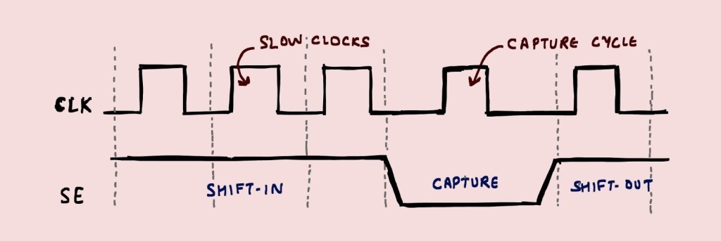
Loading/Unloading happens at the same time as the captured response from previous vector shifts-out at the same time as next test vector shifts-in.
At-speed Testing
hese tests check for the transition faults (slow to rise and slow to fall) and includes three cycles:
- Initialization : Sets the initial values at the nodes
- Transition (Launch) : Launches a value that triggers transition
- Capture: Receives the final value after transition
This can be achieved in two ways:
Launch Off Shift
- The transition pattern is launched at the last shift clock (while loading the scan chains). SE = 1
- SE is turned off to enter capture mode, and a capture clock is pulsed at functional frequency. SE = 0
- The response is shifted out. SE = 1
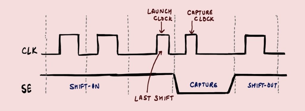
– It requires SE to be settled at a fast speed (functional clock frequency), to allow the flops all over the design to be ready for capture.
– It can be done for a non-functional path as well, as the transition pattern is shifted during the SHIFT operation itself. In real design, that transition might never happen in that path.
Launch Off Capture (Broadside)
- Shifting of the initialization vector is done using slow clock during shift-in. (SE = 1)
- SE is turned off to enter capture mode, and transition is launched on the first capture clock. SE = 0
- There is another capture clock to capture the response. SE = 0
- The response is shifted-out using a slow clock. SE = 1
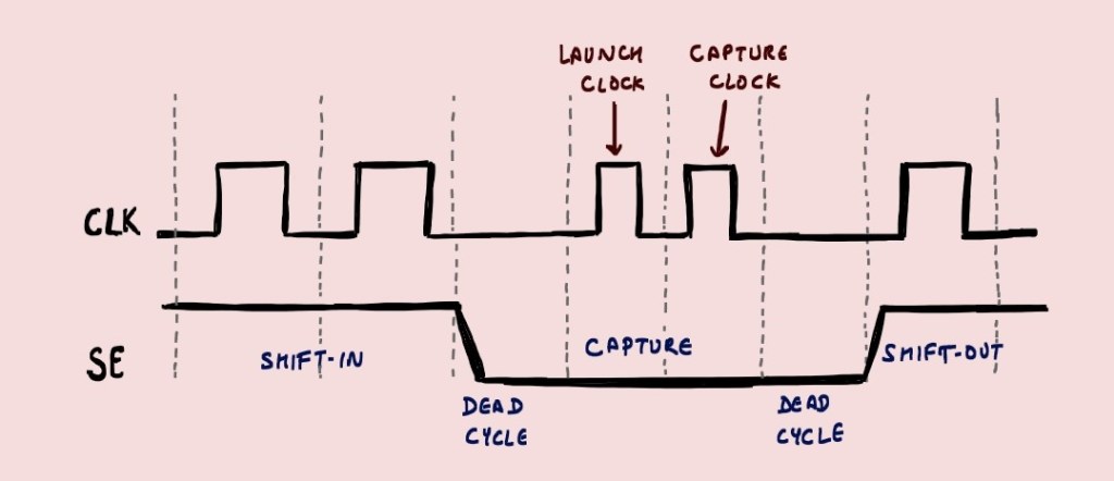
As seen, there are two pulses in capture mode (one for launch and one for capture).
+ SE has enough time to get settled and does not need to function at high speed clock.
+ There can be extra capture pulses with no activity, just to allow scan signals to settle.
– ATPG needs to calculate transition value through combinational logic in functional mode during launch.

Leave a reply to Anonymous Cancel reply