Understanding scan operation is a pre-requisite to understand scan compression. My article “Scan and Resets” defines scan in simple terms. The basic concept of scan is to convert all flip flops in the design into scannable flipflops (having scan_in, scan_out and scan_enable) and connect them to form scan chains.
Theoretically, there is no limit on the number of scan chains that can be formed, but there are hardware and performance restrictions. Let us discuss some issues we face while planning the scan architecture. Assume you have 10,000 scan flip-flops. Now let us distribute them in different cases:
1. 100 scan chains with 100 flip flops in each scan chain
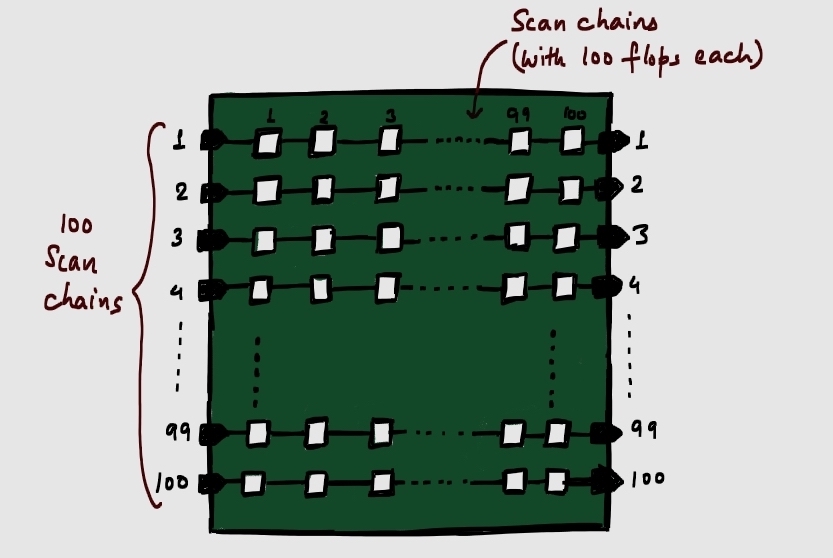
Figure 1 seems the easiest way of distributing the scan flip-flops. Now, each scan chain needs one scan_in port and one scan_out port. There are 200 scan_in and scan_out ports needed, just to implement scan testing. This requirement on number of ports is too high and hence, this is not the right approach.
2. 10 scan chains with 1000 scan flip flops in each chain
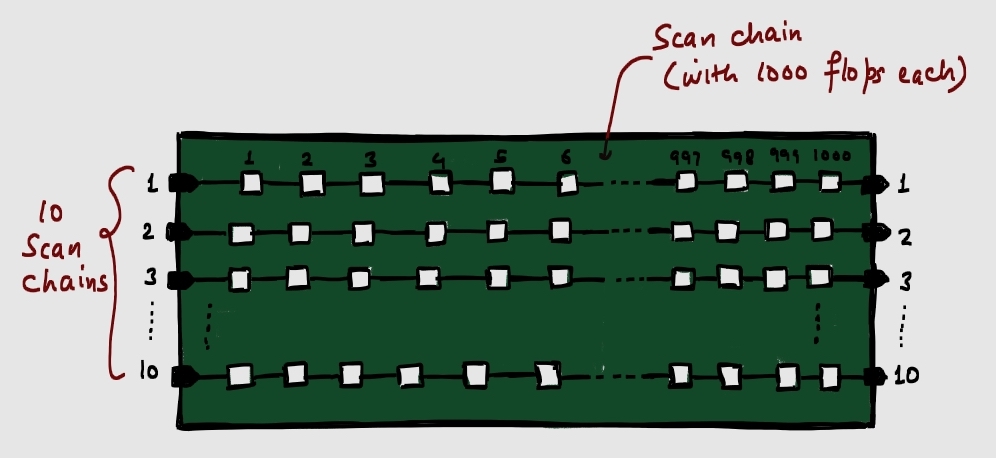
The next solution that comes across our mind is shown in Figure 2. There are 10 scan_in ports and 10 scan_out ports with 1000 scan flip-flops in each chain. The requirement of number of ports is not too high. But now, it will take 1000 cycles for a pattern to shift-in and shift-out. The test pattern will be too long, and hence will take more tester time.
Note: DFT testing is done on ATE (Automatic Test Equipment), which has access to ports at the top level only. More testing time directly affects the cost of production, and hence, needs to be optimised.
What is the solution?
Scan compression is a technique which simplifies the testing of designs with high flip-flop count. In the above example, it is possible to have 100 scan chains (with only 100 flip-flops in one chain) and use of only 10 ports. The distribution is done as follows:
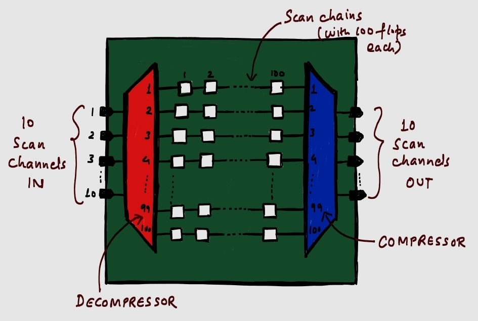
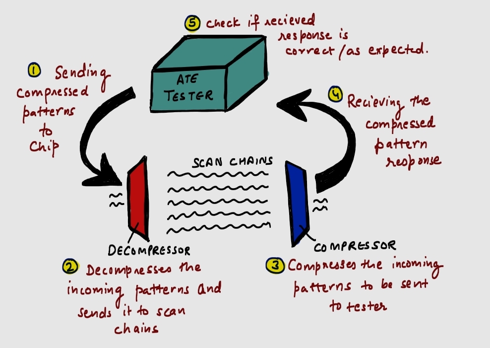
Implementing scan compression requires addition of some hardware modules. The most basic architecture includes a decompressor and compressor. As shown in above figure, the 10 ports used are called scan channels. These scan channels carry the patterns to the decompressor.
- Decompressor is a hardware module which uses certain algorithms to decompress the patterns received by 10 scan channels.
- The decompressed patterns are distributed to 100 scan chains and is shifted through the scan flops in the chains.
- The other hardware module – Compressor is shown in red. This block receives the decompressed patterns from 100 scan chains.
- The compressor also uses certain algorithms to convert the patterns back into compressed form and shifts it to the 10 scan channels on the output side.
For good testing performance, following parameters must be selected appropriately:
- Number of scan channels
- Number of scan chains
- Length of scan chains
Additional Points:
- The compression ratio is given by number of scan chains/number of scan channels. With more efficient decompressor/compressor (better algorithms), more compression can be achieved.
- Scan compression increases the complexity of design as more hardware needs to be added.
- While working with SoCs where there are multiple blocks, the integration of such structures need to be taken care of. Hierarchical DFT and wrapper chains come into picture in this case.
- Debugging faults in a scan compressed design requires more effort due to added complexity.
- A DFT engineer performing scan testing does not need to have much understanding of exact algorithms that are used to compress/decompress a pattern. Most industries use solutions provided by modern EDA companies to integrate such DFT structures into the design. Although, added knowledge is always helpful.

Leave a comment