Rom- Read only Memory is the memory which retains data even after the power is switched off. This non-volatile property of ROMs makes it useful for a lot of applications (as simple as memory which stores boot-up information of your laptop).
Let us understand the ROMs structure, as memories are integral part of any chip that we come across. ROM constitutes:
- Fixed AND logic array (Address decoder)
- Programmable OR logic array
- ‘n’ inputs : referred as address lines
- ‘m’ outputs: referred as bit lines
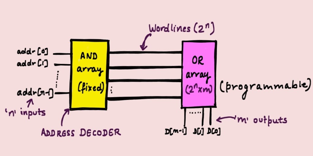
‘n’ address lines can be decoded into 2^n possible outputs, which are referred as word lines. This corresponds to 2^n possible minterms. For example, If n=3, the word lines can be represented in minterms form as:
a’b’c’, a’b’c, a’bc’, ab’c’, ab’c’, ab’c, abc’, ab’c, abc
ROMs can be manufactured using various technologies (nMOS, pMOS, cMOS etc). We will discuss nMOS structure of ROMs, which is shown in diagram below:
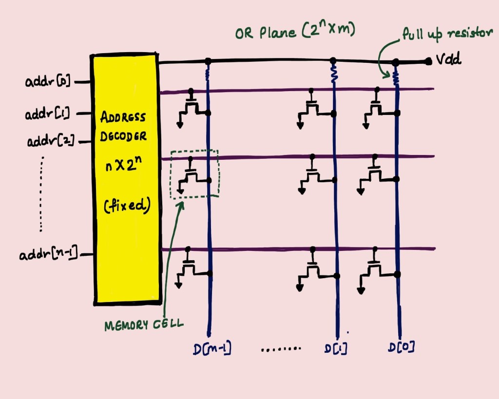
- ‘n’ address lines correspond to 2^n word lines, and there are ‘m’ bit lines
- n-channel link transistors connect bit-lines to word lines
- Bit lines are pulled up to VDD
- Programming 0: The inputs to the address decoder activates a word line, and the corresponding nMOS starts conducting. The bit line connected to the transistor is pulled down to 0.
- Programming 1: If the bit needs to be programmed as ‘1’, nMOS transistor is omitted at that point (there is no transistor to pull the bit line to 0), OR The drain/source connection is omitted in final metallization step, while manufacturing.
Consider a 16 * 8 sized ROM => 16 words of 8 bit each => 128b
Since 2^4 = 16, This memory will have 4 address lines and 8 bit lines.
These are Mask Programmable ROMS, which are manufactured with fixed non-erasable memory patterns, used in high-volume applications where data doesn’t need to be changed for ordinary use. We will dive into PLDs in next article, which will discuss programmable ROMs (PROMs).

Leave a comment