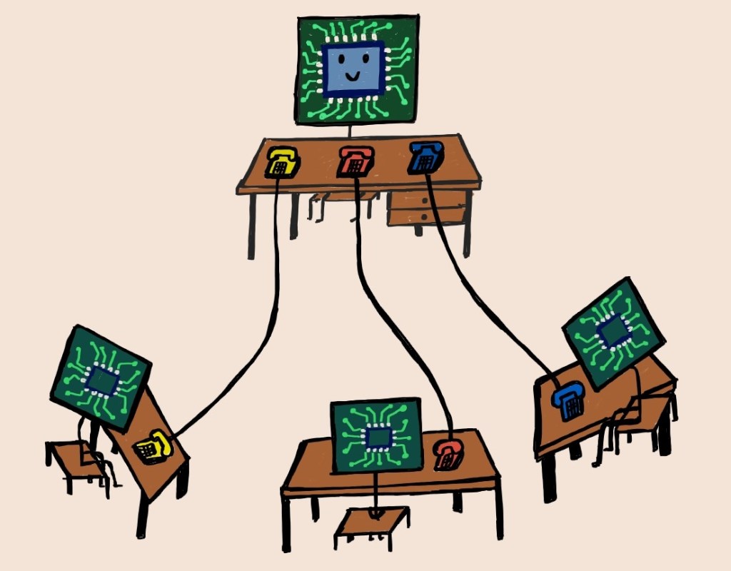
Ever wondered how electronic devices communicate with each other? Just as humans need a ‘language’ to be able to talk, electronic devices or ICs need ‘communication protocols’ to exchange information (0s and 1s here). Factors like, how fast the data needs to be exchanged, how much data is needed to be transferred, or the availability of pin count, helps in deciding which protocol to use.
Before we discuss one such protocol – SPI (Serial Peripheral Interface), lets us understand few more terms. Communication protocols can be:
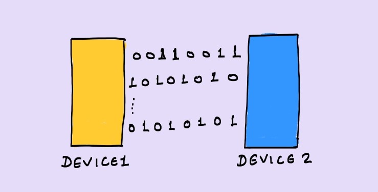
Serial
Transfer of 1 bit at a time

Parallel
Transfer of many bits at the same time
Synchronous
Data is transferred with reference to a ‘clock
Asynchronous
Data exchange doesn’t need a ‘clock’
Serial Peripheral Interface – SPI
- Serial communication
- Synchronous
- Any amount of data can be transferred in a continuous stream (not in packets limited to certain number of bits)
- Uses master-slave relationship (For example: a controller can act as ‘master’ and a memory device can act as ‘slave’
- Only master can initiate a transaction. However, some slave devices may have an extra functionality (using a separate pin) to indicate the master that they need to send or receive data. But actual transaction is started by ‘master’ only.
- Number of wires in most common configuration is 4
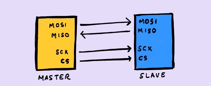
MOSI: Master Out Slave In, MISO: Master In Slave Out, SCK: SPI Clock, CS: Chip-Select
- The speed of data transmission can reach up to 10 Mbps
- The configuration can have only 1 master and unlimited slaves (practically limited, based on other factors). There are following possible configurations:
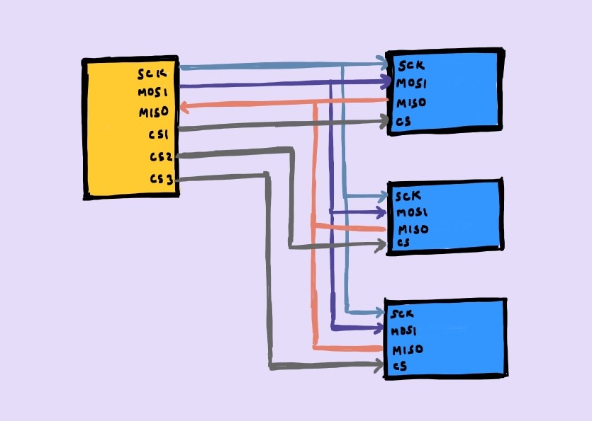
Master has 3 Chip-Select pins for 3 slaves
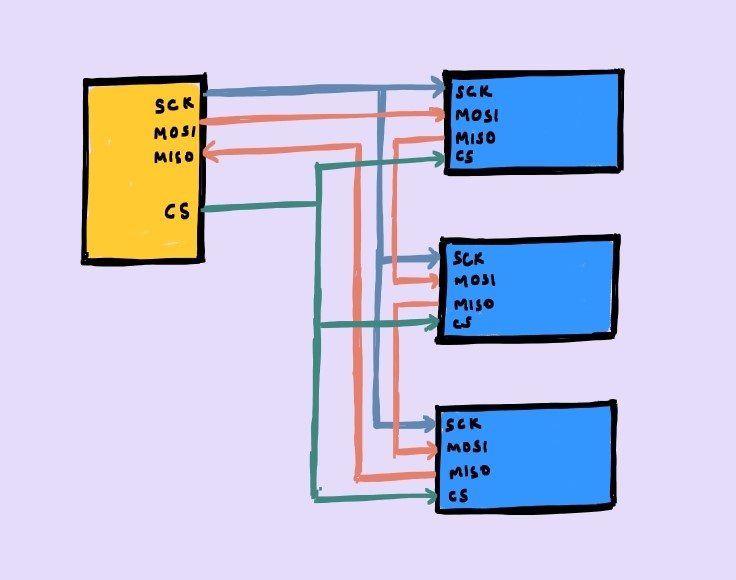
Master has only one Chip-Select connected to all slaves. The MISO and MOSI pins of consecutive flops are connected in serial as shown.
Pros
- No start/stop bits
- Simple addressing
- Faster than many other protocols
- Full-Duplex (through MISO and MOSI) – Data can be sent and received at the same time
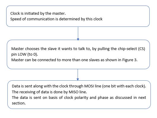
- Clock is provided by master.
Cons
- Minimum 4 wires (more than other protocols like UART, I2C which need only 2 wires)
- No data acknowledgement by the slave
- No error checking capability
- Only single master is allowed
Working
Clock Phase and Clock Polarity
CPOL
Clock “Pol”arity
0 : clock idles at 0 (pulse of 1)
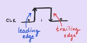
1 : clock idles at 1 (pulse of 0)
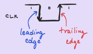
CPHA
Clock “Pha”se
0 : Data is captured on leading edge, and shifted on the trailing edge
1 : Data is captured on the trailing edge and shifted on the leading edge
The waveforms in all the possible clock phase and polarity combinations are as follows:
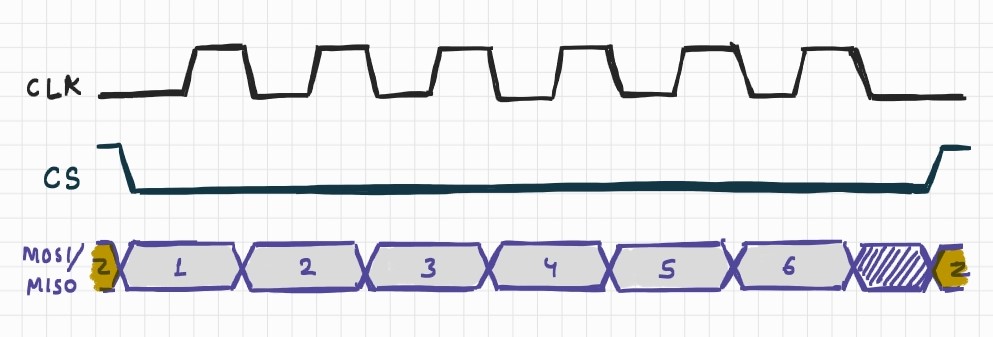
CPOL = 0 and CPHA = 0
- Leading edge : Rising
- Trailing Edge : Falling
- Data captured on leading “Rising” edge
- Data shifted/sampled on trailing “Falling” edge
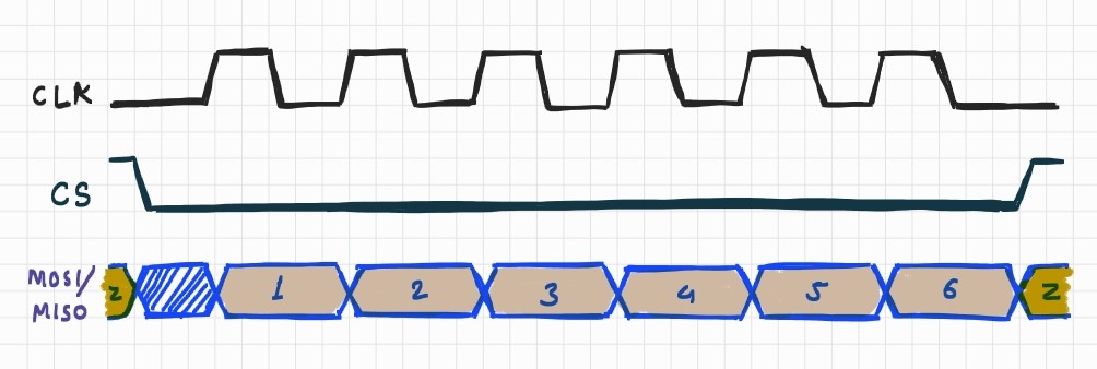
CPOL = 0 and CPHA = 1
- Leading edge : Rising
- Trailing Edge : Falling
- Data captured on trailing “Falling” edge
- Data shifted/sampled on leading “Rising” edge
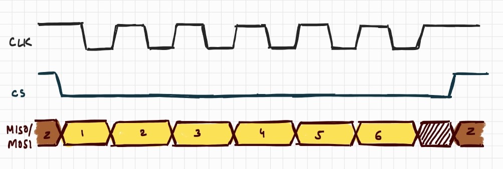
CPOL = 1 and CPHA = 0
- Leading edge : Falling
- Trailing Edge : Rising
- Data captured on leading “Falling” edge
- Data shifted/sampled on trailing “Rising” edge
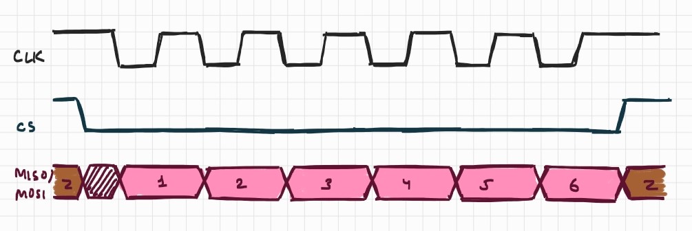
CPOL = 1 and CPHA = 1
- Leading edge : Falling
- Trailing Edge : Rising
- Data captured on trailing “Rising” edge
- Data shifted/sampled on leading “Falling” edge
Get new content delivered directly to your inbox.

Leave a comment