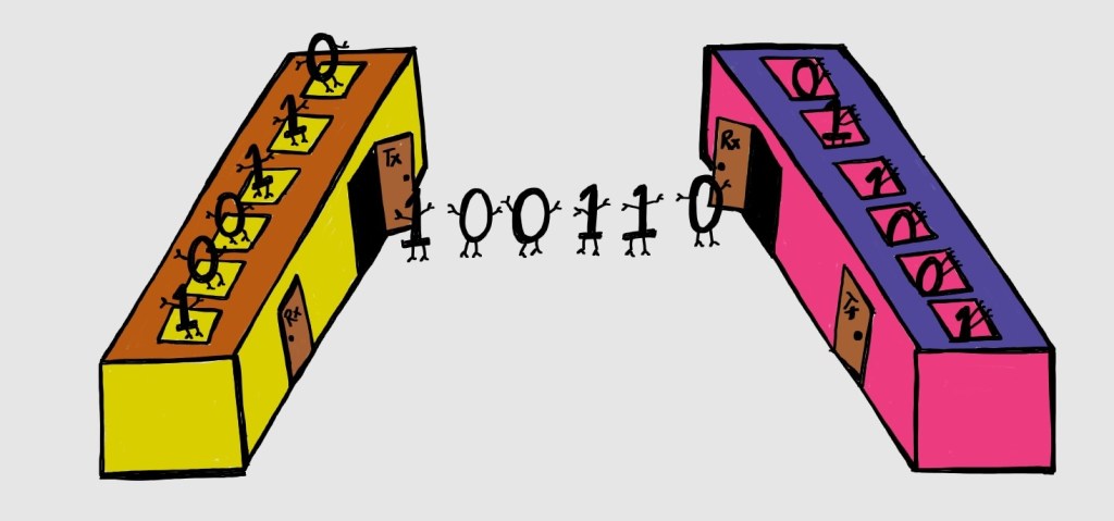
UART – ‘Universal Asynchronous Receiver Transmitter’ is a communication hardware, which utilizes only 2 pins to transfer data across devices. Let us discuss this one of the most used and earliest communication protocols.
- Asynchronous communication
- Serial
- Full duplex
- Uses two wires to transfer data: Transmitter (Tx) and Receiver (Rx)
- 1 to 1 communication
- Data is sent in the form of packets, in addition with start, stop and parity bits.
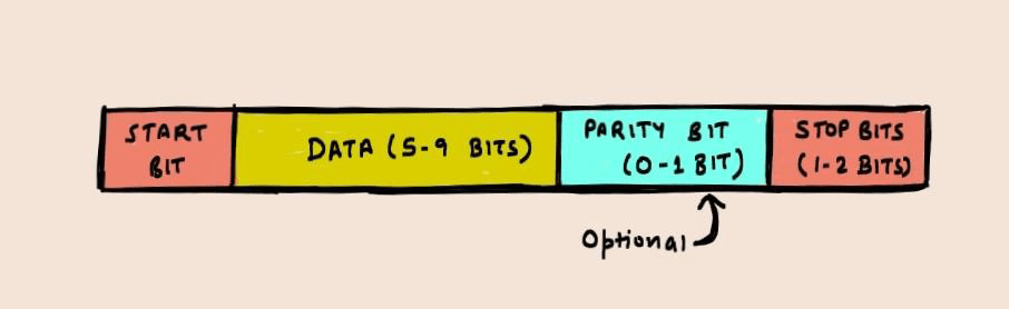
- Start and Stop bits are used to detect the start and end of data (instead of clock).
- Speed of transfer is measured by ‘Baud Rate’ expressed in bits per second. Both UARTs should be operating with same baud rate.
- Speeds: 4800 bps, 9600 bps (mostly used), 19200 bps, 115200 bps etc.
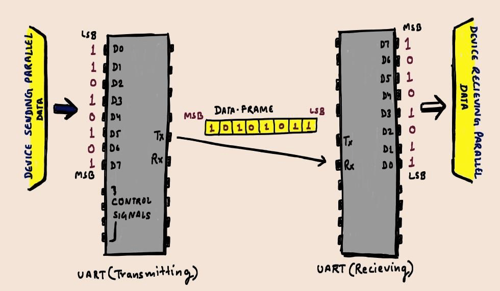
- Consists of:
| Serial to parallel converter logic | Parallel to serial converter logic | Parity logic |
| to convert incoming parallel data to serial outbound data – Transmitting UART | to convert incoming serial data to outbound parallel data – receiving UART | to introduce low level error checking mechanism |
CONS:
- Size of data is restricted to the maximum of 9 bits.
- No multiple master or slaves.
- Baud rates of Transmitting and Receiving UARTs should be within 10% of each other.
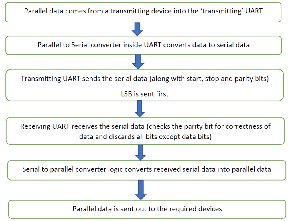
How Transfer Works?
BAUD Rate Calculation:
UART Baud Rate Generator (BRG) is a 16 bit timer. There is an extra bit , BRGS – ‘Baud rate generate select’ to select between normal and high baud range calculation.
- Normal Range (BRGS = 0) : BRG generates 16 clocks per bit
- Baud rate ‘b’ = Fosc/ (16 * (timer value + 1))
- (Fosc = Frequency of oscillation)
- High Range (BRGS = 1) : BRG generates 4 clocks per bit (only used when normal range isn’t sufficient)
- Baud rate ‘b’ = Fosc/ (4 * (timer value + 1))
Since, the baud rate depends on frequency of the device and the timer value, these shouldn’t change while the transfer is happening. They are only allowed to be programmed in ‘idle’ state.

Leave a comment